Loads - Moving Loads
The standard AASHTO loads are built into the moving loads database, however you can add and save custom moving loads as well. The moving loads can be applied in any direction, so they can be used to model crane loadings (which are typically applied in 2 or 3 directions at the same location). You can have up to 5,000 moving loads in each model.
Apply Moving Loads
To apply a Moving Load:
-
- Specify a pattern in the Pattern column by selecting it from the drop down list.
- In the Increment column specify the distance for the load pattern to be stepped through the path.
-
Specify the path by defining the Nodes in the remaining columns and indicate if you wish the pattern to be moved Both Ways through the path.

Click on image to enlarge it
Note:- You can skip
- For example, in the image below, if you want the moving load to move left to right along the beam member (M4), there if no need to specify the intermediate

Click on image to enlarge it
- You can skip

Animate Moving Loads
To animate a Moving Load:
-
If there is not a model view already open:
-
Go to the View ribbon.

Click on image to enlarge it
-
In the Window section, click the Open 3D Views icon’s arrow.
-
Choose + Add New 3D View from the menu.
This opens a new view in which you can make any adjustments you wish to appear in the animation.
You can also make further view adjustments in the animation view.
-
-

Click on image to enlarge it
-
Select the moving load or load combination from the drop-down list at the bottom of the options and then click on the Animate button.

Click on image to enlarge it

Click on image to enlarge it


Include a Moving Load in a Load Combination
To include a Moving Load in a Load Combination analysis:
- Specify the moving load in the Load Combinations spreadsheet in one of the BLC columns, and enter a corresponding BLC Factor.
-
You can either type in the moving load tag (i.e. M1, M2, etc.) directly or you can select it by clicking the


Click on image to enlarge it
-
Choose the appropriate moving load from the drop down list.

Moving Loads Spreadsheet
The Moving Loads Spreadsheet records the moving loads for the
member elements and may be accessed by

Click on image to enlarge it
Each moving load definition is automatically assigned a Tag on the left side of the spreadsheet. These labels may not be edited. Moving loads are included in your analysis by referencing this label on the Load Combinations spreadsheet.
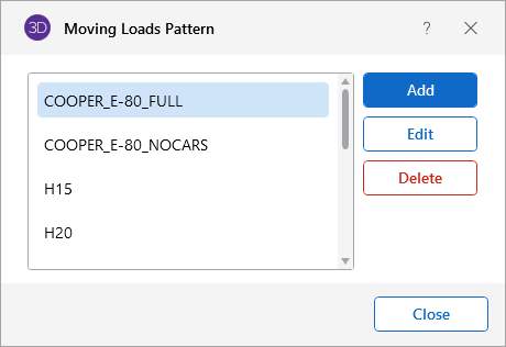
The Pattern column is the name of the moving
load pattern used for that particular moving load definition. You
can access the drop-down list of valid pattern names by clicking the down  arrow in this cell. You can access the
Moving Load Patterns and add or edit your own patterns by clicking on
the
button.
arrow in this cell. You can access the
Moving Load Patterns and add or edit your own patterns by clicking on
the
button.
The Increment column is the distance that the moving load will be moved for each step in the moving load analysis.
The Both Ways column is a check box that
indicates whether the moving load pattern is to be applied in both directions
of the load path or just one way along
the load path. If the box is checked the load is first run from
the start
The last 10 fields are the
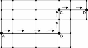
In the example moving load path shown, you would
need to specify
Moving Load Patterns
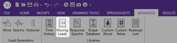
You can access the Moving Load Patterns and add
or edit your own patterns by clicking on the
The file that the moving load pattern database is stored in is ML_LIB32.FIL. The path to this file is specified in the Application Settings
When you add a new pattern, the new pattern must have a unique name and can consist of up to 50 different loads. The sign of the load Magnitude will control which way the load is pointing in the direction specified in the Direction field. The direction can be any of the 3 global directions or the 3 local directions for the members that the load will travel over. Note that if your load travels over multiple members, a local direction load will be applied based on the local axes of each member it crosses over. There is also a special code, “V”, which causes the load to be applied in the direction of the current vertical axis, whatever it is (X, Y, or Z). The Distance is the distance between the loads.

Click on image to enlarge it
Moving Loads Procedures
Moving loads are handled internally by applying the loads at discrete locations that are then moved through the model. A static solution is performed for the model at each load location. Typically, once the first solution is solved, the remaining loads are just solved against the existing stiffness matrix, so the stiffness matrix would not be rebuilt for each load position.
- Models that contain tension/compression only items will have their stiffness matrix rebuilt at least once at each load position. This can make the model solution take much longer than usual.
- Multiple moving loads may be assigned to a single load combination. However, they cannot be assigned different "start times". If a delay between moving loads is required, it must be accomplished by adjusting the moving load pattern.
- The load increment may be adjusted to "slow down" a moving load when multiple moving loads are applied.
Moving Loads Results
Load combinations that contain a moving load, will step the moving load through the load path and perform a solution for each position. The results are enveloped, giving maximum and minimum results of these solutions.
For these result spreadsheets, the maximum and minimum values are shown for each section location, for each active member. The governing load combination and step location is also shown for each result value under the "LC" column. The first number is the load combination, the second is the step number: (load combination - step number).

Click on image to enlarge it
Step Location
The step location tells you where the moving load was located along the moving load path when the maximum or minimum result value was obtained. This can help you recreate the static model to verify results.
The total number of steps is calculated as follows:

Moving Load Step Point Load Generation
Because solving moving loads produces so much output (full model design at each moving load step increment), the output is limited to Enveloped results. This means that the moving load results only show the maximum and minimum values for each output result value.
However there are times when you can want to investigate the full model design (all member results, detail reports, deflected shape, etc.) at a specific step. You can easily create a static load case of the moving loads at a specific load step using the Point Loads from a Moving Load feature.
![]()
Click on image to enlarge it
Instructions for Moving Load Step Point Load Generation
To move Load Step Point Load Generation:
-
Determine which moving load step you want to investigate.

Click on image to enlarge it
-
Access this feature
The Point Load(s) From a Moving Load data appears in the Properties panel.
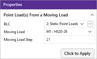
- Select which Basic Load Case you want the static point loads to be added to.
- Select which Moving Load or Load Combination with a moving load you want the point loads generated from.
-
Select the Moving Load Step you want the static point loads generated from.
-
Click

Click on image to enlarge it
- Create a Load Combination that includes the Basic Load Case selected in step 2 a above and solve to see the full results.

